

Section: Oil Burners – Basic Function
Hot water pressure washers use an oil burner to heat the outgoing water. The water is heated after it has left the high-pressure pump and the unloader. This keeps the hot water from affecting those components. Many people confuse by-pass thermal damage with heat generated by a malfunctioning burner, but the two are not related. The burner system creates heat at a rated amount of BTUs, and that heat is then transferred to the water through the pipe of the coil. The amount of heat generated is controlled by the amount of fuel being burned per minute. The oil pump pressure and the oil nozzle size control the fuel amount. To efficiently combust the fuel, the air supply must be sufficient, and ignition must be provided. The more water that flows through the coil per minute, the more BTUs are required to heat it to the desired temperature.
Section: Burner Power Supply
The three common voltages that oil burners are supplied with are 240-volt, 120-volt, and 12-volt. A 240-volt oil burner typically found in a fixed location that can supply that amount of voltage, and would not normally be found in a mobile wash environment. A 120-volt system would be in either a fixed location, or utilized with a pressure washer equipped with a generator to supply the needed power. Using a 12-volt burner eliminates the need for a separate generator on a mobile unit. This burner can draw power from the engine charging system. Lets look at the advantages of the 12-volt burner in a mobile pressure washer. The most obvious advantage would be the elimination of the separate generator. This reduces to cost of the pressure washer. It also allows for a smaller engine because a generator requires one to two horsepower to generate the electricity. When eliminating a major component, there is one less thing to maintain and repair. Units that do have a generator are belt drive to allow one engine to transfer power to both the pump and the generator. A 12-volt unit provides the option of gear drive. Gear drive units can be more compact then belt drive units. Belt driven generators used on pressure washers weigh around seventy pounds. A small advantage is gained in vehicle fuel consumption without this weight. There a only a few disadvantages to the 12-volt burner system. It is important that the engine charging system produces enough voltage to continuously supply the burner, along with providing the power required by the engine. The minimum charging system used to successfully operate an oil burner on a pressure washer is 16-ampere; to be safe a 20-ampere or larger charging system is recommended. The cost of a 12-volt burner, as well as the cost of many replacement parts is higher than that of a 120-volt unit. This of course is offset by not having to buy and maintain a generator. Whatever power source is used, that source provides the electricity than powers the burner motor, the igniter, and the switches and valves related to burner operation.
Section: Motor
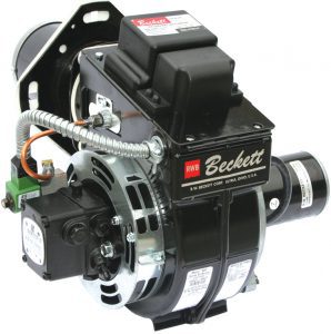
Most burner motors used on pressure washer burner units are ¼ or 1/5 horsepower. 12-Volt motors are physically smaller than 120-volt motors. They all have a mounting plate that allows for bolting to the burner housing. Most burner motors turn at 3450 RPM.
Section: Motor Diagnosis
Is the Motor turning? If it isn’t, with the power turned off, check to see if the motor turns freely by turning the squirrel cage fan by hand. If the motor turns, the motor may have a reset on it, try the reset button. Next, test to determine if there is power at the incoming power cable in the burner housing. Perform this test with a multi-meter or a test light. If there is power, and the wire leads to the motor are properly connected, the motor needs to be replaced. If there is no power coming into the burner, the power supply problem must be diagnosed and repaired. If the motor doesn’t turn, the motor or the pump could be the problem. Disconnect the fuel pump from the burner housing and pull it away so it is not longer engaged to the motor. Now attempt to turn the motor, if it turns replace the fuel pump, if it doesn’t turn, replace the motor.
Section: System Wiring
If the equipment has a wiring diagram, follow it through to gain an understanding of the electrical flow. If the equipment doesn’t have a wiring diagram, follow the incoming power to determine the path of the circuits. The power generally comes through a circuit breaker or a fuse before entering the burner housing. The wires are accessible when the transformer / ignitor is unscrewed and folded back on its hinge. First find the power cord wires and follow them to the first grouping of wires. At this point the burner components that run constantly will be connected in one circuit, while other components that are controlled by the switches will be wired in another circuit loop. If the burner is wired in the most common way, the transformer / ignitor and the burner motor will be wired directly to the incoming power cord so that anytime power is supplied to the burner they will be on. The secondary circuit will be made up of all the switches and the fuel solenoid. These control components will be wired in a loop. An example of this loop would be, incoming power black to wire one of the flow switch, flow switch wire two to high limit switch wire one, high limit wire two to thermostat wire one, thermostat wire two to fuel solenoid wire one, fuel solenoid wire two to incoming power common (white). If any switch or solenoid in the secondary circuit fails, the burner doesn’t ignite, but the components that are wired directly to the incoming power that are not affected by the secondary circuit will continue to operate. If there isn’t a wiring diagram, mapping out the wiring of a pressure washer isn’t a bad idea. Without a wiring diagram or map, remember this one piece of advice above all else, don’t disconnect the burner wiring without recording how it was connected. On way to keep the wiring straight is to label them with small pieces of tape with numbers. As you label each wire, record on a piece of paper, which number wire, reconnects where. If you disconnect all the wiring without mapping it out, it can take a long time to figure out, but looking on the bright side, it can be an excellent learning experience.
Section: Wiring – No Incoming Power
No power at the burner? Check for loose or disconnected wires. Reconnect and retry the burner if any are found. 120 and 240-volt systems. Check and replace fuse if blown; Reset the circuit breaker if it is tripped. If after you do this, the circuit breaker or fuse goes out again, begin looking for shorts, or for binding of the motor. If there is a circuit breaker that doesn’t manually reset, test it for continuity with a meter, or another way to test it is by bypassing it with a 20-amp in-line fuse. 12-volt systems. Check and replace fuse if blown; Reset the circuit breaker if it is tripped. If after you do this, the circuit breaker or fuse goes out again, begin looking for shorts, or for binding of the motor. If there is a circuit breaker that doesn’t manually reset, test it for continuity with a meter, or another way to test it is by bypassing it with a 20-amp in-line fuse. Next, is the battery dead? If it is test the battery and replace it if necessary. If the battery test indicates it is good, recharge it and test the engine charging system to determine if it is operating properly.
Section: Fuel Delivery
The fuel pump on the oil burner is normally a 3450-RPM pump that is driven directly by the motor. The motor shaft is connected to the pump shaft with a flexible coupling. This coupling is designed to strip in the event of a pump freeze up. There are two ways that a fuel pump on an oil burner can be plumbed. With one fuel line from the tank to the pump, or with a return line that circulates the fuel back to the tank when it isn’t burned. For lubrication purposes, it is important for a fuel pump on a burner that doesn’t fire for long periods to have a return line. The fuel pump continually pulls fuel from the fuel tank, then cycles it back. A fuel filter installed on the inlet line assures that no contaminants reach the pump. When the burner is firing, the fuel is pushed out the pump outlet port and through the fuel solenoid. From there the fuel is plumbed directly to the fuel nozzle. The nozzle is designed to atomize the fuel and spray it in a cone shaped pattern that ignites easily and burns cleanly. The burner nozzle is designed with a filter that provides a last second chance to trap any debris that may have escaped the first fuel filter. An extremely small particle will block or impede the flow of fuel through the nozzle.
Section: Burner Nozzle Assembly
Remove the nozzle assembly from the burner housing. This is done with the equipment shut off. It is accomplished by opening the transformer / ignitor on its hinge. Then remove the thumbnut and the fuel line from where the fuel line is attached to the burner housing. Carefully remove the nozzle assembly from the burner by lifting it out of the opening on the top of the burner housing. Inspect the electrode tips for damage or wear, and replace if necessary. Make sure that the proper gap is set, and that the distance from the nozzle is correct. Check your burner specifications to obtain the correct measurements.
Section: Air Flow
For proper combustion, the burner fan must supply the correct amount of air to mix with the fuel. Most burners have the fan inside the burner housing with visual access gained by folding open the ignitor on its hinge. The fan is attached to the burner motor shaft with an allen-type set screw. This fan is called a squirrel cage fan. Airflow adjustment slots are located on the outside of the burner housing. One has two slots and consists of a band that wraps around the circumference of the housing. The other is a disc that is located on the housing facing. Both can be adjusted after loosening the setscrews that hold them in position. When the airflow on the burner is correct, as long as there aren’t any other problems, the burner will burn cleanly, producing no visible exhaust. Closing down the adjustment slots too much restricts the airflow, and the burner will smoke. Opening up the adjustment too much can cause the fuel nozzle spray pattern to be compromised, causing poor fuel ignition and smoke. If adjusted out more, the air can actually blow out the flame and keep it from igniting again. Anytime adjustments are made, remember the original setting so any adjustment that doesn’t result in an improvement can be reversed.
Section: Air Flow Testing, Repair & Adj
Unscrew the top screws on the transformer / ingnitor and fold it open on its hinge. Keeping away from the spring terminals to avoid being shocked, look inside and verify that the squirrel cage fan is spinning. If it is damaged or loose, replace or tighten it. Inspect the airflow adjustment slots on the burner housing to make sure they aren’t blocked. Check the coil outlet port for any possible blockage. Remove the burner assembly from the coil and look into the coil. Remove any blockage caused by loose insulation. Check to see if the coils are blocked with accumulated soot deposits. If the coil is blocked up with soot, remove and clean it, then reinstall. If a new size fuel nozzle has been installed, or if the fuel pump pressure has been adjusted, it may be necessary to adjust the air vents on the burner housing. Also be aware that if you install a fuel nozzle that is too large for your system, it will smoke regardless of what you adjust. A rule of thumb is the maximum rated flow of your burner nozzle should be half of the rated water flow of the pressure washer pump. To adjust the burner airflow, locate the two air adjustments on the burner housing. One is an outer band that circles around the burner housing. The other is a flat disk that is located on the housing face around fuel pump. Make a note of the existing settings so that if the smoke gets worse when you change the setting, you will know where you started from so you can go back. Smaller adjustments are made with the disk, and that is where to start. If you run out of adjustment on the disk, then start working with the band. With either adjustment, loosen the retaining screw(s) so you can move the disk or band, and then retighten when adjustments are completed. The disk has an arrow that points to numbers as a reference. Slide the disk one number at a time and wait about twenty seconds to see the operational result in the combustion. Continue adjusting until the cleanest burn is obtained.
Section: Ignition
The transformer or ignitor provides an ignition spark for the fuel. The incoming electricity is stepped up to a higher voltage then delivered to the area of the fuel nozzle by electrodes. A spark jumps between the tips at the end of the two electrodes, which ignites the atomized fuel as it emerges from the nozzle.
Section: Ignition Spark Diagnosis & Repair
First, be sure that there is sufficient incoming voltage to the burner, if there isn’t, insufficient spark may be the result. In a 12-volt system low incoming voltage is one of the common causes for ignitor failure. Be sure that the transformer / ignitor wires are connected to the power source. Next test the Transformer / Ignitor. The correct way to test a transformer or ignitor is to remove the top screws and fold it open on its hinge. Always use caution not to touch the terminals underneath with your body because of the shock hazard. Also take care not to drop anything on to the spinning fan. This test must be performed with the burner turned on. If the burner is wired for constant voltage to the transformer / ignitor, it isn’t necessary to have water flow. With a large screwdriver that has an insulated grip, touch the tip of the blade to one terminal, then lower the screwdriver shaft to ¼” away from the metal mounting plate. If spark is not established, replace the transformer / ignitor. If there is spark, increase the distance between the screwdriver shaft and the mounting plate to ¾”. The spark should continue, it should jump ¾”. If the spark does not jump ¾”, replace the transformer / ingnitor. Test the terminal on the other side the same way. Both terminals must provide sufficient spark for the burner to operate properly.
Section: Electrodes
Check to make sure that the transformer / ignitor terminals make solid contact with the electrodes when the unit is closed onto the burner housing, and if they don’t, make any necessary adjustments. The electrodes are two thick wire conduits that have ceramic insulators. The purpose of the electrodes is to deliver the voltage (and the spark) to where it will ignite the fuel. Next examine the electrode’s ceramic insulators for signs of cracks and carbon tracking. Carbon tracking is a gray build up that indicates a short is occurring. If the electrode is shorting out, it is not delivering the spark to the fuel properly. If carbon tracking is found, replace the electrode.
Section: Fuel Supply Diagnosis
Is there fuel in the tank? Don’t just assume there is, and don’t trust the fuel gauge. Check it visually or use a dipstick. Disconnect the fuel line fitting where the fuel line enters the burner housing. Loosen the fitting on the other end where the fuel line attaches to the fuel solenoid outlet and move the line to make it possible to hold a container under the line to catch fuel. Tighten the fitting at the fuel solenoid. Hold a container at the fuel line outlet, a small coffee can works well, and then perform the following test. Start the pressure washer and turn on the burner. Have another person spray for about five seconds while you check to see if fuel is flowing properly. There should be a strong, steady stream of fuel without air bubbles in it. If fuel is flowing properly, you have just eliminated the fuel tank, fuel filter, fuel lines, fuel pump, the flow or pressure switch, and the fuel solenoid as possible problems. Next component to examine is the fuel nozzle. With the machine turned off, open the transformer / ignitor on its hinge. Remove the thumbnut from where the fuel line had been attached to the burner housing. Carefully remove the nozzle assembly from the burner by lifting it out of the opening on the top of the burner housing. Remove and replace the burner nozzle. If there is an obstruction in the nozzle, it is possible to remove it, however it is also very easy to damage the nozzle so that the fan pattern of the spray is no longer correct. If the fan spray is distorted, the burner may smoke badly, or not ignite at all. Reassemble and retest. If there was no fuel flow from the fuel line, check for fuel flow at the fuel pump bleeder. The bleeder is located on the side of the fuel pump. With the burner on, slowly open the bleeder while holding a container to catch the fuel under it. There should be a strong stream of fuel without air bubbles in it. If there isn’t proper flow at the fuel pump bleeder, begin inspecting the path of the fuel for problems. Has the fuel filter been changed? If not start by changing it. Some fuel tanks have screens that can become obstructed, check and clean. On older equipment the fuel line and fittings can become restricted, inspect and clean or replace any that have built up deposits. Sometimes air can enter the fuel line or filter because of a crack or leakage at a fitting or clamp. After exhausting these possibilities, move on to the fuel pump. If there was no flow at all from the pump bleeder, remove the pump from the burner housing and attempt to rotate the pump shaft. If the pump shaft can’t be turned, replace the fuel pump. Also inspect the flexible coupling that engages the motor to the fuel pump and replace it if damaged. If there is some flow produced at the bleeder, remove the cover of the fuel pump. It is held in place with four small screws. Under the cover you will find an internal filter screen, clean it if necessary. To remove and inspect the fuel pump piston, remove the pump pressure adjustment fitting and the pump outlet fitting on the opposite side. Inside there is a piston, a spring, and a metal disk. The metal disk and spring should be removed from the pressure adjustment fitting. A blunt probe should then be inserted into the piston chamber and the piston should be pushed out of the pump through the outlet port. If the piston is frozen or hard to push in the chamber it probably has rusted due to water in the fuel and disuse. As long as the piston can be removed without damage, the piston and the piston chamber can then be cleaned. This cleaning should be done in a way that avoids scratching the surfaces involved. After cleaning, reassemble. If the piston now moves freely, complete reassembly and test. If it isn’t possible to get the piston to move freely, replace the fuel pump.
Smoking Burners? Grayburnerman.comshows you how to keep your burner coils and heating chamber from ‘sooting’up. CLICK HERE
To much air results in not enough heat and terrible fuel economy.Grayburnerman.com shows you how to adjust your burner of optimum performance. CLICK HERE
Why is fuel pump pressure so important? Grayburnerman.com shows you why proper atomization of fuel is so important. CLICK HERE
Burner Spark Test. Grayburnwerman.com shows how to test the transformer/ignitor spark. CLICK HERE
Adjusting the Burner gun/nozzle assembly. Grayburnerman.com shows you how to set-up the proper electrode alignment of pressure washer oil burners. CLICK HERE
Section: Oil Burner Controls
When used on a pressure washer, a burner must be told not to burn when no water is flowing, and when the water is hot enough. This is done with a series of switches that open or close to either complete a circuit or open a circuit. Contained in this circuit are all the switches that sense flow and water temperature, and the fuel solenoid valve. When the circuit is closed and energized, the solenoid valve is open and fuel flows through and goes to the burner nozzle. When the circuit is open, and not energized, the solenoid valve closes and shuts off the fuel supply to the nozzle. With no fuel to burn, the burner flame goes out. The fuel still flows in the fuel pump, being pulled from the fuel tank and recycled back to the fuel tank through the return line. On some burners this circuit also shuts off power to the motor and the ignitor. This is called a double lock out system. There rationale for the motor and the ignitor to be shut off is to conserve electricity. This is typically done with a 12-volt burner so it draws less power from the battery and the engine’s charging system. Most switches used for burner control are wired in the normally open position; some however are wired in the normally closed position.
Section: Flow Switch General Info.
Remember that you will either use a Flow, Pressure or Vac Switch. Pressure Switches are the most popular.
A flow switch completes the circuit when the water is moving after the unloader valve outlet. It must be installed after the unloader outlet so when the trigger gun is released it will be in the correct position to sense the flow stoppage. If a flow switch is installed before the unloader the water will continue to flow in the by-pass loop and the switch will remain closed, allowing the burner to continue to fire. The by-pass loop includes the pump outlet to the unloader inlet, so the water continues to move there in any case, whether the trigger gun is opened or closed. A flow switch is installed directly in the water stream. It has a metal body that is hollow inside. A magnet floats in the hollow section of the body. When the water is flowing the magnet is pushed to one end of the hollow section. When the water stops flowing the magnet returns to the other end. A reed switch, which is two wire like contacts enclosed in a protective tube, is located on the outside of the flow switch body. The two contacts are pulled together by the magnetic force when the magnet is near them. The magnet is located near them when the water is flowing. The reed switch is connected into the circuit that controls the oil solenoid valve, and on some burners also controls the motor and ignitor. A flow switch used to control a burner is wired to be normally open.
Section: Flow Switch Magnetic Repulsion
This type of flow switch can be mounted horizontally or vertically. It isn’t found as frequently as the other types of flow switches. This switch has two magnets. One located in the hollow tube in the body, and one fixed at the outlet end of the body. The two magnets are installed with their similar poles towards each other. With the magnets installed in this manner, they try to repel each other. The force of the water flow overcomes this resistance and pushes the free magnet forward, into a position that causes the contacts in the reed switch mounted on the outer body to come together so the circuit is completed and the burner will fire. When the flow stops the magnets repel each other and the free magnet is pushed back, breaking the circuit and stopping the fuel flow to the burner nozzle. A flow switch used to control a burner is wired to be normally open.
Section: Flow Switch Tri Magnet
A tri-magnet type flow switch uses three magnets to close a micro switch. The magnets in this switch are installed with their similar poles towards each other. So they are creating a force that repels each from the other. One of the magnets moves freely inside the flow switch body. The flowing water stream, overcoming the repellent force of the other magnets, pushes this magnet forward. When this magnet is in the forward position it activates a micro switch, closing the circuit and allowing the fuel solenoid valve to be energized and opened. When the water flow stops, the similar pole repellant force pushes the floating magnet back, opening the switch and breaking the circuit. The fuel solenoid is then de-energized; the valve closes and shuts off the fuel supply to the burner nozzle. A flow switch used to control a burner is wired to be normally open.
Section: Flow Switch Vertical Only
A flow switch that is a vertical mount only, uses gravity to return the magnet to its original position after the trigger gun is released. It has no spring. The magnet has a small hole drilled through it that allows water to be released from the system that is downstream from the flow switch. This is the type of flow switch to use with a flow actuated unloader valve. A flow switch used to control a burner is wired to be normally open.
Section: Flow Switch Vertical/Horizontal
Some flow switches that contain reed switches can be mounted vertically or horizontally. The magnet in these flow switches has a spring that applies enough pressure to it to return it to its original position when the water flow stops. When the trigger gun is released, and the spring pushes the magnet back, the magnet traps the pressure downstream from the flow switch. Because of the trapped pressure, this type of flow switch doesn’t work well with a flow actuated unloader valve. A flow switch used to control a burner is wired to be normally open.
Section: Flow Switch Testing & Repair
If bypassing the flow switch indicated that the flow switch was the problem, disconnect the switch body from the pressure washer plumbing. Leave the wiring intact. Hold the switch in your hand and turn on the burner power. If you have a vertical only pressure switch, turn it upside down. The magnet inside should drop to the other end of the switch body and the burner should fire. If it doesn’t, either the magnet has lost its draw or the reed switch is not functioning. Replace the reed switch and perform the test again. If the burner fires, the reed switch was bad. If the burner doesn’t fire, replace the entire switch. If your machine has a horizontal flow switch the only difference in the test procedure is that you need to push the magnet forward using a screwdriver. If you have a flow switch with a magnet that can’t be reached from the outside, and turning the switch upside down doesn’t cause the burner to fire, replace the flow switch.
Section: Pressure Switch
Remember that you will either use a Flow, Pressure or Vac Switch. Pressure Switches are the most popular.
Pressure switches can be used for a variety of purposes on a pressure washer. We will address their use as a burner control, but they can also be used to activate a timer device, like in a car wash bay to limit operation time, or to switch a motor on and off for an electric pressure washer A pressure switch that is used as a burner control basically does the same job as a flow switch. The switch must be installed in the water flow were it will be exposed to high pressure when the trigger gun is open, and low pressure when the trigger gun is closed. Unlike a flow switch, which is installed after the unloader, a pressure switch must be installed between the pump outlet and the unloader inlet. In this part of the water stream the pressure is low when the machine is in by-pass and high when the trigger gun is open and the water is being forced through the high-pressure nozzle. A pressure switch is plumbed into the water flow so it is directly exposed to the operating pressure. It has a fitting that allows installation, o-ring seals, a plunger, spring, electric micro switch, and the switch body itself. On the switch body there is a plate that is held in place with screws and has a seal to waterproof the switch. Removal of this plate allows inspection of the micro switch. When the PSI is high, the pressure switch plunger is pushed in. When pushed in, the plunger activates the micro switch and completes the circuit. When the system pressure is reduced, the spring applies more force to the plunger than the water pressure and the plunger is pushed out, disengaging it from the micro switch and opening the circuit. Pressure switches are available that switch at different pressures. A common one used switches at 580 PSI. The system needs to operate at a higher pressure than the PSI that causes the switch to activate when under pressure, and at a low enough PSI that the switch isn’t activated when in by-pass. A pressure switch used to control a burner is wired to be normally open.
Section: Pressure Switch Testing/Repair
If bypassing the pressure switch indicated that the pressure switch was the problem, first remove the inspection plate on the switch body. Start the pressure washer and examine the switch plunger operation while another person first sprays for five seconds, and then stops spraying for five seconds. The plunger should move back and forth contacting and depressing the micro switch. If the plunger is depressing the micro switch and the burner doesn’t fire, replace the pressure switch. If the plunger isn’t contacting and depressing the micro switch, use a small screwdriver to manually depress the micro switch. If the burner still does not fire, replace the pressure switch. If the burner does fire, then remove the pressure switch from the pressure washer. Inspect the small orifice that allows water to enter so pressure can push the plunger. If it is blocked, open it back up using a pin or some other type of probe. Try to manually push the plunger, if it is stuck this will help to free it. When the plunger moves freely and the orifice is open, reinstall the pressure switch and test.
Section: Vacuum Switch
Remember that you will either use a Flow, Pressure or Vac Switch. Pressure Switches are the most popular.
This type of switch, like a pressure switch, can be used for several applications. When used as a burner control, it opens and closes the circuit that causes the oil solenoid to either be energized and open, allowing fuel to enter the burner nozzle, or shutting the fuel supply off to the burner nozzle. Use of a vacuum switch requires negative pressure to be generated by the pump drawing water into the inlet port. If the equipment is operated with a pressurized feed, a float tank must be installed to break that feed pressure. The incoming supply flow enters the float tank, and then a separate port in the float tank connects the float tank to the pump inlet. The vacuum switch is installed between the float tank and the inlet port of the pump. A vacuum switch used to control a burner is wired to be normally open. Breaking down the components that make up a vacuum switch, the list includes, the switch outer body, the diaphragm, spring, and the electric switch. Most vacuum switches have a manual test lever that protrudes out through the outer switch cover. A vacuum switch operates using the negative pressure, or suction produced as the pump is drawing water into the inlet port. When negative pressure is present, the switch diaphragm balloons towards the negative pressure. The switch is attached to the opposite side of the diaphragm and is activated when the diaphragm pulls it. When the pump stops drawing water because the trigger gun is closed, the negative pressure is eliminated and with the assistance of the spring, the electrical switch is returned to its open position breaking the electrical flow through the circuit. This causes the fuel solenoid to close stopping the fuel flow to the burner nozzle.
Section: Vacuum Switch Testing & Repair
If bypassing the vacuum switch indicates that it is the problem, first verify that the inlet plumbing is installed so that the float tank is breaking the inlet water pressure. The vacuum switch must operate where the inlet line is producing a vacuum. Make sure that the pump is drawing properly at its rated volume. When the unloader is adjusted so most of the water the pump delivers is sent into bypass, the inlet may not draw enough water to create enough suction to operate the vacuum switch. Most vacuum switches have a manual lever on the side that activates the micro switch. If depressing this lever fires the burner, the switch is functional, but the diaphragm is not activating it. To make sure that there is a vacuum for the switch, with the machine running, burner on, and water flowing, reach into the float tank and block the outlet port for several seconds. This should create additional vacuum and cause the burner to fire. If it does, try to make adjustments to increase the water flow. If all efforts fail, the diaphragm may be damaged and the entire vacuum switch should be replaced.
Section: Thermostat, General Information
A pressure washer thermostat is located in the electrical circuit with the fuel solenoid. It is a switch that breaks the circuit, stopping electricity from energizing and opening the fuel solenoid, or it completes the electrical circuit allowing the fuel solenoid to be energized and opened, thus allowing fuel to be supplied to the burner nozzle. The thermostat uses a sensing devise to determine the temperature of the water. When the water becomes as hot as the thermostat is set to allow, the sensor opens the switch and breaks the flow of electricity in the circuit, causing the fuel solenoid valve to close. When the water temperature lowers because the burner is no longer heating it, the sensor allows the switch to close again restoring the electrical flow and energizing the solenoid, which allows the burner to fire. Any temperature-sensing switch must be installed with the sensor located where the water first emerges from the heater coil to be accurate. Thermostats can be wired either normally closed or normally open.
Section: Thermostat Dead Band
This refers to the range of temperature between when a thermostat shuts off the burner and when it allows the burner to fire up again. Thermostats have different dead band ranges. Better thermostats have a small range, some as tight as just a few degrees. This causes the burner to cycle on and off more often to keep the water temperature more consistent. Most pressure washer thermostats have a dead band range of 20 to 30 degrees or more. Where consistent water temperature is important, most thermostats fail to perform as well as desired.
Section: Fixed Thermostats
These are our most popular thermostats. These thermostats are pre-set to a certain temperature and the ‘dead-band’ is very narrow which produces a much more even cleaning path. Because they don’t have an adjustment dial, these thermostats are a simple probe that contains the sensor and the switch. It is installed where it can best sense the water temperature as it emerges from the coil. It is wired into the circuit with the fuel solenoid.
Section: Thermostat Adj. Panel-Mount
Adjustable thermostats provide a means for the equipment operator to set the temperature at which the sensor will open the switch. A dial or adjustment screw is the most common adjustment method. The ability to make these adjustments is important if the operator wants to match the water temperature to the cleaning job being performed. A panel-mount thermostat consists of a dial and switch that is mounted in a location remote from the sensor. The sensor is a liquid that fills a sensor bulb and capillary tube. The bulb is mounted at the outlet of the heater coil where it is exposed to the water temperature. A capillary tube connects the bulb with the switch. The liquid is a special viscous fluid that expands when it is heated. This expanding and contracting fluid activates or deactivates the switch. The thermostat is wired into the electrical circuit with the solenoid.
Section: Thermostat Adjustable In-line
Adjustable thermostats provide a means for the equipment operator to set the temperature at which the sensor will open the switch. A dial or adjustment screw is the most common adjustment method. The ability to make these adjustments is important if the operator wants to match the water temperature to the cleaning job being performed. An in-line thermostat has an inlet and outlet plumbing port. It is installed at the outlet of the heater coil. It senses the water temperature as it flows through. An adjustment dial is located on the outer body of the thermostat. The thermostat is wired into the electrical circuit with the oil solenoid valve.
Section: Thermostat Testing & Repair
If bypassing the thermostat indicated that it was the problem, make sure that it is adjusted to a temperature that is high enough to activate it. If the inlet water is not cold, the thermostat may not sense the need to raise the water temperature, otherwise it is likely that replacement will be necessary. Thermostat dead band range can increase with wear also, when it becomes a problem, replacement is recommended.
Section: High Limit Switch
A high limit switch is a lot like a fixed thermostat. It is either used as a safety device in addition to a thermostat that keeps a burner system from heating water too much, or it alone controls the high-end temperature of the water. A high limit switch will generally be pre-set around 200 degrees. Temperatures above 200 degrees become damaging to components of the pressure washer. It is installed as close to the outlet of the heater coil as possible. When it senses the flow of water has reached its pre-set limit, the sensor opens the electrical switch and breaks the circuit, thereby stopping the burner from firing and allowing the water to cool. When cooler water is sensed, the switch closes again allowing the burner to fire. A good point to remember is that if the water flow stops, and the burner continues to fire due to the failure of some other component, the high limit switch will not be very effective because the water is no longer flowing past it. Eventually the temperatures at the sensor may reach the point where the sensor opens the switch, but by then the temperatures inside the coil will be extreme. If this occurs, do not start the water flow until the water in the coil has cooled. This cooling in some cases will take hours. There is also a danger of the coil itself being damaged, perhaps even exploding because of trapped water and steam pressure. A pressure washer operator needs to understand these dangers and be vigilant.
Section: High Limit Switch Replacement
If bypassing the high limit switch indicated that the switch was the problem, replace it.
Section: Fuel Solenoid
The fuel solenoid is the valve that is energized when the burner control switches allow current to flow to it. It is a valve that when open, allows fuel to flow to the burner nozzle, and when closed it shuts off the fuel supply to the nozzle. With fuel, the burner fires and the water is heated, without fuel, the burner cannot fire, and no heat is produced.
Section: Fuel Solenoid Testing & Repair
Test to determine if the coil is creating a magnetic field. First establish that power is being supplied to the solenoid, either by testing the voltage with a meter, or by connecting the coil directly to the proper power source. Next remove the coil from the valve by removing the retaining nut. With the coil energized, slowly insert a small screwdriver blade into the center hole. If the coil is functional, the magnetic force should pull the screwdriver blade to the coil. If the coil no longer produces a magnetic force, replace it. If the coil does produce a magnetic field, check the valve stem and ball. Remove the two screws that hold the rectangular plate on to the valve body. The valve stem can now be pulled out of the valve body. Inside the valve stem is a ball that should move back and forth. Shake the stem and listen for the sound of the ball moving. If no sound is heard, insert some type of thin probe like a pin into the small hole in the end of the valve stem. If the ball is stuck inside it should be possible to free it in this manner. Once the ball is free, reassemble and test operation.
Section: Oil Burners Coils – Design
The purpose of a burner coil is to provide an efficient transfer of heat from the burner flame to the water flowing inside the coil pipe. Many design features help to accomplish this transfer. A coil is enclosed in a coil jacket, or tank. The jacket is constructed of metal and it is generally insulated on the inside to prevent the outside from becoming dangerously hot during operation. The pipe in a coil is spaced to allow the flow of hot air produced by the burner flame, and propelled by the burner fan, to circulate easily and contact the entire outer surface of the pipe. Nearest the burner, a single outer coil of pipe allows a large open space in the center so the flame itself makes minimal connect with the pipe. At the end away from the burner flame, the coil pipe is wrapped into layers in which the pipe is circled around from the outer edge into a small inner circle. Each row that has the pipe wrapped into the inside to form a small inner circle is called one pancake. Each pancake provides addition feet of pipe inside the coil jacket. The more pancakes in a coil, the more pipe surface is exposed to the heat. Water traveling through a coil with many pancakes also has to travel inside the coil longer, so it is exposed to more heat transfer for a longer period of time. Another factor in designing a coil to provide maximum heat transfer is the diameter of the pipe, the large the diameter, the more water is contained inside. The more water inside the coil pipe, the slower it moves through the coil. To understand this think about the water as it flows through the high-pressure nozzle. As the diameter that the water has to flow through gets smaller, the speed at which the water is propelled increases. Conversely, the larger the diameter of the opening or pipe, the slower the water flow. A baffle is a steel plate that is welded to the end of the coil farthest from the burner. The baffle causes the hot air from the burner to deflect away from the jacket outlet initially. The airflow is directed to pass through the openings between the pipes in the coil so the most heat transfer occurs.
Section: Material
Most pipe material is either steel or stainless steel, as is the jacket. The schedule of the pipe pertains to the thickness of the pipe wall. The larger the pipe inner diameter, the thicker the wall needs to be to withstand the same amount of pressure. The most common schedule pipe used for pressure washer coils is schedule 80. The most common inner diameters are 3/8″, ½”, and ¾”. Schedule 40 pipe is still used for lower pressures, and schedule 160 is used in some higher-pressure equipment. Generally, the thicker the pipe wall, the greater the longevity of the coil.
Section: Horizontal Coil
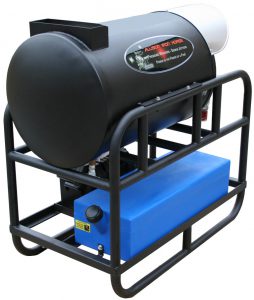
This type of coil has the burner mounted on one end and is installed horizontally on a frame. Because the burner isn’t mounted on the lowest point, water doesn’t get into it and cause damage. The exhaust is commonly routed out the end of the coil jacket that is opposite the burner assembly.
Section: Vertical Coil
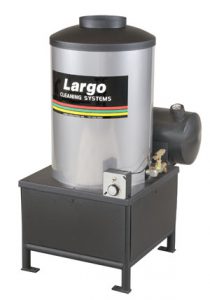
This type of coil has the burner mounted underneath and exhausts out the top. The biggest drawback to the vertical coil is that leaks or condensation from the coil piping drains directly into the burner. Water creates problems in the burner including electrical shorts and misfiring of fuel. An advantage of a vertical coil is that the exhaust is aimed up and away from people around the equipment. Some believe the vertical design creates a more even application of the heat to all areas of the pipe because heat rises. Because the heated air is fan forced through either coil design, we find this belief to be groundless. Servicing an oil burner mounted underneath a coil is much less convenient than servicing an oil burner on a horizontal coil.
Section: Exhausting Considerations
Many times it is helpful to add stovepipe to the exhaust of the coil jacket to route the exhaust fumes out of the area where the equipment is located. If the equipment is permanently mounted in a building, exhausting the burner to the outside is advisable. If the equipment is permanently mounted in an enclosed truck or trailer, it can be exhausted through the roof or the vehicle side. Another option that can be considered with a horizontal coil is to install the equipment with the exhaust port pointing out a door. This eliminates the need for additional piping. It is important to provide a way to exhaust the hot gases out of the area that the equipment runs in. Heat build up, as well as the build up of exhaust fumes around the unit, is detrimental to the equipment operation. Cool fresh air is needed for the engine to operate properly. Heat is also a major factor in igniter failure.
Section: Coil Repair Or Replacement
If a coil begins to leak, it is sometimes possible to repair it by welding the leaking area. The area must be accessible for welding. If it isn’t, replace the coil. If the coil is old, replacement is recommended even if the leak is accessible. The coil is probably ready to leak in numerous other areas and the repair will not buy much time.
Section: Coil Maintenance – Descaling
A coil should be descaled periodically to allow for optimum heat transfer between the hot air and the water. Descaling is a process where acid is circulated through the coil for a period of time. There are products made and sold for this process, and they are recommended. Follow all safety precautions on the product packaging and M.S.D.S. Another acid product that can be used is a 5 to 8% solution of hydrofluoric acid. If you typically use this type of acid and have it on hand, you may want to use it to descale your coil. Hydrofluoric acid is dangerous and aggressive; take every precaution when using this acid. Whichever acid is used, it should be self-inhibited. That means it won’t attack the metal of the coil much, it will primarily work on the scale. Hydrofluoric acid isn’t always self-inhibited. Circulate the acid solution through the pipe for the period of time recommended on the packaging, or if using hydrofluoric acid, for one hour. Do not use the pressure washer pump to circulate acid. That is damaging to the pump and it makes no sense to maintain one component by damaging another. An old pump, or an inexpensive pump that can be sacrificed without losing too much money should be used. Use a circulating pump that is acid resistant. With the acid in a pail, place the pump pick up line into the solution, then connect the pump outlet to the coil inlet. Plumb the coil outlet back to the pail. Run the solution in a loop for the correct amount of time. Next run an alkaline detergent through the coil using the same method. Finally rinse the coil with clear water, and then reassemble the equipment. It isn’t possible to offer an exact amount of operation time to run the equipment before descaling should be done. It depends on the hardness of the water being used, and how hot the water is heated. The hotter the water the more the minerals in it fall out and attach to the inside of the pipe. It is also difficult to judge because inspection of the inside of the pipe is difficult. If the burner runs a lot and the water doesn’t get as hot as it should, scaling may be the problem. Unless there is an identifiable problem, if the equipment is used 30 to 50 hours a week, descale annually. Usage of less than 30 hours a week, descale every other year.
Section: Coil Maintenance Soot Removal
Soot builds up on the pipe exterior surfaces from the burner exhaust. The soot insulates the pipe reducing the transfer of heat. Soot can also build up and block air passage around the pipe. Inspection involves removing the burner assembly from the coil jacket and visually examining the coil for soot. If the burner is fueled with kerosene or number one fuel oil soot is generally not much of a problem. If the burner is fueled with number two fuel oil, soot will build up and the coil will need to be cleaned periodically. Adding a soot remover to the fuel oil helps to reduce any build up. If the coil needs to be cleaned, disconnect and remove it from the machine. Pressure wash the coil, using a good degreasing chemical. Let the coil dry then reinstall onto the pressure washer.
Section: Coil Care Notes
Never allow a coil to freeze. The coil could crack, and the rest of the equipment could be damaged also. Anti-freeze equipment to protect it from freezing. Whenever equipment is left in storage for more than a few weeks, anti-freeze it. The anti-freeze contains rust inhibitors that will protect your coil. Never allow the burner to operate without water flow. This can damage the coil, and it can cause explosion and personal injury. A coil on a pressure washer that is being run cold for a long time can be anti-freezed and by-passed, which will add to its longevity. If this is done, disable the burner so it cannot be turned on by mistake. A coil on a pressure washer that is being run cold in humid weather will have condensation on the outside of the pipes. This condensation collects in the burner on a vertical coil and in the insulation underneath it on a horizontal coil. Firing the burner occasionally will help to dry things out.