

General & InterPump Pumps
Click On Photo To View Larger Image
Note: The rails that come standard with General Pumps are not recommended to be used with gas engine pressure washers. We recommend a taller rail to accommodate the larger pulleys required for gas engine set-ups. Click Here and order part number 1653
General Pump Video Library
Pump Service –Shark shows you how to repair a high-pressure pump on a commercial pressure washer. CLICK HERE
Pump Service – General/InterPump CLICK HERE
What size engine will you need to drive the pump you select? Easy! Simply take the rated GPM of the pump you select and multiply it times the rated PSI of that pump and then divide by 1100.
Example:
A 5.5 GPM Pump that is rated for 4,000 PSI
5.5 x 4000 ÷ 1100 = 20HP required
So you don’t have a 20 horsepower engine? No problem! So long as it will fit you can use the pump on any engine. Yes, that’s right – ANY ENGINE – even a 5 hp. The only thing is – you won’t be able to get 4,000 psi but you can still get the 5.5 gpm so long as you have the right pulley configuration to produce the pumps recommended rpm.
The ratio of a gear box in the pressure washer industry is typically 2.2-1. In other words when the pump is attached forever 2.2 revolution the gear box makes the pump will turn one revolution.
So you have a pump that is rated for no more than 1450 rpms. Attaching a gear box means that you cannot turn the gear box more than 3190 rpms before you exceed the recommended pump speed. 1450 x 2.2 = 3190 gear box speed.
So here lies the problem when using a 1450 rpm General pump on a gear box. All engines –out of the box – are factory present to around 3800 rpm. This means that you will be over-running the pump if you do not reduce the engine speed to 3190. Yes you could do that but then you lose horsepower and you may not have enough available horsepower left to run the pump at full spec. If an engine is rated at 18 horsepower at 3600 rpm and you adjust it down to 3190 rpm you will then have an engine that is producing around 16 horsepower.
But now let’s take a 1750 rpm General pump and do some math: 1750 rpm x 2.2 =3800 rpm
This is pretty close to where the pump and engine needs to be without any adjustments. Simple as that.
Bottom line – if you have a 1450 rpm pump hooked to a gear box and are running your engine at full-bore then you are over working your pump. If you have turned the engine rpm down to accommodate the recommended pump speed then you have given up horsepower to do so.
Gear Drive pressure washers should always be equipped with 1750 rpm pumps.
DIRECT DRIVE – 3400 RPM
|
|||||||||||||||||||||||||||||||||||||||||||||||||||||||||||||||||||||||||||||||||||||||||||||||||||||||||||||||||||||||
| MODEL |
GPM |
PSI |
RPM |
Shaft |
Weight |
Breakdown |
Valves |
Packings |
Oil Seals |
||||||||||||||||||||||||||||||||||||||||||||||||||||||||||||||||||||||||||||||||||||||||||||||||||||||||||||||
|
EZ4040G |
4.0 |
4,000 |
3400 |
1″ |
19 lbs |
||||||||||||||||||||||||||||||||||||||||||||||||||||||||||||||||||||||||||||||||||||||||||||||||||||||||||||||||||
|
|||||||||||||||||||||||||||||||||||||||||||||||||||||||||||||||||||||||||||||||||||||||||||||||||||||||||||||||||||||||
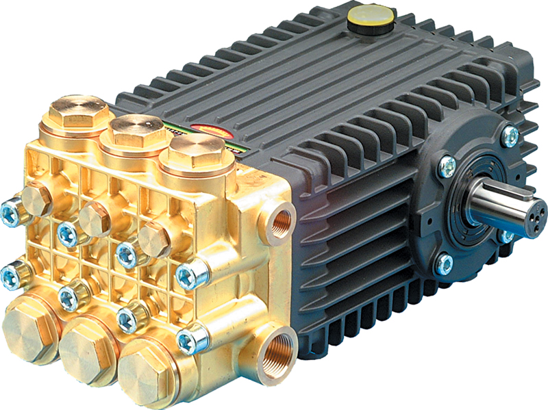
Section: Basic General Pump Design
The two major components of the modern General high-pressure plunger pump are the manifold and the crankcase. The manifold is also referred to as the head or the wet end. The manifold is the section of the pump that the water flows through. The crankcase, or power end contains the oil. These two major components are bolted together. The crankcase itself is normally constructed of a die-cast aluminum; the manifold is typically constructed of Brass, aluminum, nickel-treated cast iron, or stainless steel.
Section: Manifold Function for General Pumps
The manifold has two inlet ports and two outlet ports, one on each side. On one side the ports are generally sealed with plugs. The plugs can be removed and/or switched around as desired. Having two of each port allows the General pump to be plumbed from either side, increasing versatility during installation. The inlet port is a larger diameter than the outlet port. The inlet ports are located on the lower half of the manifold, and the outlet ports are on the upper half. Both the inlet and outlet ports have female threads. The manifold on a triplex plunger pump has a total of six check valve caps. Removing the caps exposes the check valves. The three outlet check valve caps are located on top of the manifold, and the three inlet valve caps are located on the lower half. The check valve caps each have an o-ring seal. The actual check valves are press fitted inside the manifold, under each check valve is an o-ring seal. The inlet and outlet check valves are exactly the same and can be interchanged. When the manifold is removed from the crankcase, the surface that is revealed allows the cylinders to be seen. The manifold of a General triplex pump has three cylinders. Each cylinder is equipped with packing assemblies that consist of the packings and pieces that retain the packings in the proper position within the cylinder. Most pumps have packing assemblies that are pressed into the cylinder, but some are held in with an outer threaded retainer. The check valve assembly contains a guide, or cage, two seats, and a spring. The guide holds the components together and in alignment. When the seats are together the valve is closed. The spring applies pressure to the seats. When the water flow overcomes the force exerted by the spring, the seats separate and the water is able to pass through the valve.
Section: Crankcase Function for General Pumps
The crankcase assembly, using the force provided by the power plant, moves the plungers back and forth. Outside the crankcase, the crankshaft is connected to the power plant either directly, through a gear reducer, or by pulleys and belts. Where the crankshaft enters the crankcase there is an oil seal and a bearing that it turns in. There is another bearing on the other side of the crankcase that the end of the crankshaft turns in. The crankshaft is turned at a certain RPM. Inside the crankcase, connecting rods are moved back and forth by the cams on the crankshaft. Attached to the connecting rods are plunger guides. The plunger guides protrude through the crankcase and into the manifold cylinders. Oil seals contain the oil in the crankcase that bathes all the moving components in oil as they turn for lubrication. Outside the crankcase, the plungers and plunger retaining bolts are mounted on the plunger guides. With the manifold bolted on the crankcase the plungers fit tightly into the cylinders. Most crankcases have both an oil stick and a site glass for checking the oil level. The crankcase is typically vented through the oil stick to prevent pressure from building up inside as friction produces heat. Without a vented cap the oil seals would be damaged during operation from trapped pressure from within the crankcase.
Section: Solid Shaft General Pumps.
These General plunger pumps require either a gearbox or a belt and pulley system to drive them. They come in several different RPM ranges. If a standard 2.2 to1 gearbox is used, a 1450-RPM pump is correct. When using belts and pulleys, the pulleys are sized to provide the correct reduction in speed from the engine RPM to the pump rated RPM. Solid shaft pumps that turn at the same RPM of an engine or motor can be connected directly to the power plant using a coupler.
Section: Direct Drive General Pumps for Gas Engines
These General plunger pumps operate a 3450-RPM, which allows them to be connected directly to the engine crankshaft. A gasoline engine normally operates under load at 3450 RPM. This type of pump has a hollow shaft that mates with the engine crankshaft. There is a variety of hollow shaft sizes, the most common being ¾ “, 1 “, and 1 1/8 “. Around the hollow shaft is a mounting flange that allows the pump to be bolted directly to the engine.
Section: Direct Drive General Pumps For Electric Motors
These General plunger pumps operate at 1725 or 3450 RPM, which allows them to be connected directly to an electric motor. Electric motors normally run at these speeds. This pump has a hollow shaft that mates with the motor drive shaft. The hollow shaft is available in several different sizes corresponding to common motor shaft sizes. There is a mounting flange that allows for direct mounting to the motor face-plate.
Section: Job Matching General Pumps
Matching a General high-pressure pump to a specific type of job can be accomplished by determining what pump characteristics are important to that job. Characteristics and operating parameters that need to be considered include PSI, GPM, RPM, power plant, weight, cost, and high temperature or cold feed. Here are a few examples of the thought process that goes into matching jobs to pumps. A pump used on equipment that is only used for cleaning hoods and duct work would ideally have a low flow rate, 4 gpm or less, to facilitate water recovery. To help make up for the low flow rate a higher PSI rating of around 4000 would be best. If it utilizes the hot water from the buildings plumbing system, it would need to have high temperature resistant components. If the unit is going to be portable and lightweight so it can be moved into and around the job site easily, a direct drive pump is best. For truck washing, using a pump with more flow is advisable. The pressure can go down as the flow goes up. The best result comes from a flow rate between 5 and 6 GPM and a PSI rating of 2200 to 2800. When washing trucks, the majority of the time is spent applying chemical and rinsing it off. The more flow available the faster these steps can be completed. The equipment is generally truck or trailer mounted, so gear or pulley drive is practical. Being familiar with the operation that the pump needs to perform allows you to decide what pump is best suited for the task.